It does not have the vector editing function of ALVECTOR (simple CAD function) and direct access to vector data structures, but all the main functions of raster-vector conversion can be used in a more user-friendly way.
| DLL | Overview |
|---|---|
| alibvector.dll | Vector Library API (C++) |
| Other Multiple DLLs | Our Common Library (API undisclosed) |
| Header File | Overview |
|---|---|
| alibvector.h | Raster Vector Conversion Library |
| errcode.h | Error Code Definitions |
Reference
// Constructor
// Input
//  char*   code;           Full path of the key file containing the key code
//                          or the key code string itself
//                          Check for initialization success/failure using misinitrastervectorconversion()
CALibVector(char* code);
// Destructor
~CALibVector();
// Query if initialization was successful
// Return
//   1....success
//   0....failure (key file not found, expired, or no permission)
int     misinitrastervectorconversion();
// Clear the polyline (when loading a different image after conversion, etc.)
// Deleting the instance and creating a new one again doesn't incur much cost
void                mclearpolyline();
Sample
CALibVector* plib = new CALibVector("c:\\Program Files\\Foo/vector.kcd");
if(plib->misinitrastervectorconversion() == 0) {
   ;  // No permission
}
delete plib;
The original library (CALVector class library) includes basic CAD functionalities such as searching for nodes near specified coordinates, moving nodes, inserting nodes, drawing polylines, circles, etc., and copying polylines. However, these functionalities are not supported in the CALibVector library. They are omitted for the simplification of the API, but there is a possibility of supporting them in the future if there is demand.

Reference
// Set document settings
// Input
//   int            width;           Image width (in pixels)
//   int            height;          Image height (in pixels)
//   int            scanlinesize;    Image scanline size (in bytes)
//   int            dpi;             Image resolution (in dpi)
//   unsigned char* pdata;           Get the address of the image's head
void                msetdocument(int width,int scanlinesize,int height,int dpi,unsigned char* pdata)
// Top-level contour extraction
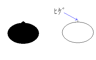
// In the simple version, automatically removes whiskers whose length is up to 3 lines
// In the simple version, automatically performs the following post-processing:
//   Matching the start and end points within 0.3mm
// (Supported in the 2007 version) The presence or absence of arc approximation in post-processing can be controlled by arcflag.

// Note: If you want to control the above parameters, use mabstractcenterline/mabstractroutine
// Input
//    double  threshold;        L2 approximation threshold (refer to the manual)
//                              (Value greater than 0 and less than 10.0, recommended value 0.8 to 2.0)
//    int     postprocessflag;  1...Perform additional post-processing
//                              0...Do not perform additional post-processing
//    int     arcflag;          1...Perform automatic arc approximation (radius 1 to 1000mm)
//                              0...Do not perform automatic arc approximation
// Return value
//   0....Normal termination
//   Negative...Error (refer to errcode.h)
// Contents of additional post-processing
// 1...Automatic removal of adjacent nodes (vertex distance of 1mm, angular deviation of 15 degrees)
// 2...Removal of unnecessary points on a straight line (angular deviation of 3 degrees)
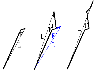
// 3...Automatic sharpness enhancement of corners (with images under the corner, targets up to 5 vertices, long side and short side both 2.0mm, target angle up to 45 degrees)
// 4...Automatic correction of T-junction and crossroad (vertex movement distance up to 2.5 pixels, deviation from right angle up to 18 degrees)
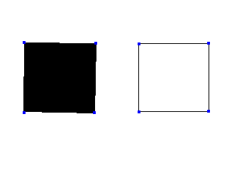
// 5...Automatic circle conversion (when the vertices on a closed curve are arranged 100% within an estimated radius of 0.85 to 1.15, move the position of the vertex to the estimated radius.
//                    However, it is necessary for the vicinity of the moved vertex to have pixels within a distance of 2.5 pixels from the bottom of the target radius)
// Note: If you want to manipulate the parameters of additional post-processing, set postprocessflag to 0 here and call the API with parameters for post-processing.
int                 mabstractoutlinesimple(double threshold,int postprocessflag,int arcflag = 1);
// API to specify all preprocessing parameters,
// Call the API for post-processing for post-processing
int                 mabstractoutline(double threshold,   // (Value greater than 0 and less than 10.0, recommended value 0.8 to 2.0)
    int        higelength,     // Length of whiskers to be removed (in pixels, not removed if 0)
    int        higelinenum,    // In a open curve, sections with a maximum of higelinenum line segments connected are targeted for removal
                               // Most of them become closed curves in contour extraction, but whiskers occur when there is a line with a width of 1 pixel
    double    integratedist);  // If the distance between the start and end points of a polyline is less than or equal to integratedist, match the start and end points
                               // When approximating a closed curve, vertices may occur near the end point by going around from the start point
                               // Normally, the distance between the start and end points is large enough, so this is a kind of insurance.
                               // A value of about 3 pixels can be specified for integratedist.
sample code
// Notify the width(mwidth), scanline size(mscanlinesize), height(mheight), resolution(mdpi), and base address(mdata) of the image
// CALibVector::plib
#include "alibvector.h"
#include "errcode.h"
plib->msetdocument(mwidth, mscanlinesize, mheight, mdpi, mdata);
// Extract contours with no default preprocessing or postprocessing
int i1 = plib->mabstractoutlinesimple(2.0,0);
if(i1 < 0) {
    // Error;
}
...
Reference
// Set document settings Reference for contour extraction
void msetdocument(int width, int scanlinesize, int height, int dpi, unsigned char* pdata)
// Top-level core line extraction
// In the simplified version, the following preprocessing is automatically executed:
// - Automatic removal of whiskers with a length of 2 pixels or less
// In the simplified version, the following post-processing is automatically executed:
// - Automatic connection of endpoints within 1mm (angle deviation up to 90 degrees)
// - Automatic connection of endpoints within 3mm (angle deviation up to 40 degrees)
// - No integration of closely located intersection points
// Note: If you want to control the above parameters, use mabstractcenterline/mabstractroutine
// (Supported in the 2007 version) Joint presence in post-processing can now be controlled with jointflag.

// Input:
//   double threshold: L2 approximation threshold (refer to the manual)
//                     (Value should be greater than 0 and less than 10.0, recommended value: 0.8 to 2.0)
//   int postprocessflag: 1... Perform additional post-processing
//                        0... Do not perform additional post-processing
//   int jointflag: 1... Automatic joint (connecting adjacent endpoints on a straight line)
//                  0... Do not perform automatic joint
// Return:
//   0... Normal completion
//   Negative number... Error (refer to errcode.h)
// Content of additional post-processing:
// 1... Automatic removal of close proximity nodes (vertex distance of 1mm, angle deviation of 15 degrees)
// 2... Removal of unnecessary points on a straight line (angle deviation of 3 degrees)
// 3... Automatic sharpening of corners (image below the corner, target: up to 5 vertices, both long side and short side are 2.0mm, angle up to 45 degrees)
// 4... Automatic T-junction and crossroad correction (vertex movement distance of up to 2.5 pixels, deviation of 18 degrees from right angle)
// 5... Isolate processing (treat as two intersecting lines of →↑ instead of four lines of +↑→↓←)
// Note: If you want to manipulate the parameters of additional post-processing, specify no post-processing here and call the API for post-processing with the specified parameters
int mabstractcenterlinesimple(double threshold, int postprocessflag, int jointflag = 1);
// API that specifies all preprocessing parameters,
// Post-processing is called using the API for post-processing
    int mabstractcenterline(double threshold,    // (Value should be greater than 0 and less than 10.0, recommended value: 0.8 to 2.0)
    int higelength,        // Length of the whisker to be removed (in pixels, if 0, no removal)
    double autojointshort,    // Maximum distance for automatic connection up to an angle deviation of 90 degrees (in mm, if 0.0, no connection)
    double autojointlong,     // Maximum distance for automatic connection up to an angle deviation of autojointangle (in mm, if 0.0, no connection)
    double autojointangle,    // Angle deviation of the two sides that can be automatically connected (in radians)
    double integratedist);    // Maximum distance for integration of closely located intersection points (in mm)
Sample
// Notify the width (mwidth), scan line size (mscanlinesize), height (mheight), resolution (mdpi), and start address (mdata) of the image
// CALibVector::plib
#include "alibvector.h"
#include "errcode.h"
plib->msetdocument(mwidth,mscanlinesize,mheight,mdpi,mdata);
// Extract core lines with no default preprocessing or postprocessing
int i1 = plib->mabstractcenterlinesimple(2.0,0);
if(i1 < 0) {
    // Error;
}
...
Reference
// Tilt detection and correction
// Input
//  double      angle1;         Collect edges close to 0°, 90°, 180°, 270° (within ±angle1 radians)
//  double      angle2;         Standard deviation of collected edge tilts (in radians)
//  double      threshold;      Length of edges to be collected (in pixels)
//  int         leastnum;       Number of edges to be collected (if at least leastnum edges are collected, calculate tilt)
// Output
//  double      *angle;          Tilt
// Return Value
//  1....Normal termination
//  0....Unable to obtain tilt due to conditions not being met
int                 mhorizontalize(double angle1, double angle2, double threshold, int leastnum, double& angle);
Sample
// Tilt correction
// Estimate and acquire tilt when the number of edges with a length of 12.7mm or more in the range of ±5 degrees from vertical and horizontal is 2 or more and standard deviation is 0.5 degrees or less
// PAI is the mathematical constant pi (3.14159265358979...)
// dpi is the resolution for converting from mm to pixels
// CALibVector::plib
double angle;    // The acquired tilt
int i1 = plib->mhorizontalize(5 * PAI / 180,0.5 * PAI / 180,12.7 * dpi / 25.4,2,angle);
if(i1 == 1) {
    ;   // Processing such as image rotation
}
Reference
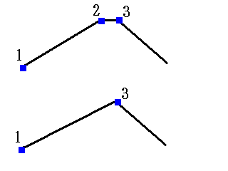
// Removal of nearby vertices (common for coreline and outline)
// Input:
//  double dnear: Maximum distance between vertices considered as nearby (in pixels)
//  double radian: Maximum angle deviation between 1→2 and 2→3 (to retain sharp angles even if the distance is close)
//                           □------□--□------□
//                           1      2↓3      4
//                                     ↓
//                           □--------□--------□
void mdeletenearpointall(double dnear, double radian);
Sample
// Removal of nearby vertices, within 1mm and 15 degrees
// CALibVector::plib
plib->mdeletenearpointall(1 * dpi / 25.4, 15 * PAI / 180);
 In the figure above, vertex 2 is removed because the angle between vector 12 and vector 23 is less than or equal to the specified angle deviation parameter.
Reference
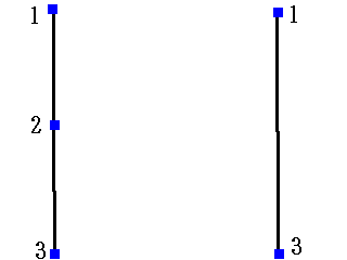
// Removal of excessive points on a straight line (common for core lines and contours)
// □------□------□
// 1      2      3
//         ↓
// □--------------□
// Input
//    double angle;       Angle between 1→2 and 2→3 (unit: radians)
//    double probelen;    Check if the foot of the perpendicular dropped from 2 to 1→3 is on the foreground color of the raster
//                        If bit1 is within probelen pixels from the foot of the perpendicular, it is considered OK
void                mdeletewastepointall(double angle,double probelen);
Sample
// Removal of excessive points on a straight line, within 1.5 pixels and an angle of 3 degrees or less
// CALibVector::plib
plib->mdeletenearpointall(3 * PAI / 180,1.5);
Reference
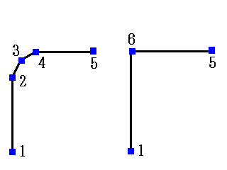
// Corner sharpening (when cnodenum is 4) (common for contour/skeleton)
//                                      O (newly created vertex)
//         Short side                  / \
//         O---O                      /   \
//        /     \                    /     \
//       /       Long side          /       \
//      /         \                /         \
// ---O            O---        ---O           O---
// Formats the acute angles based on the lengths and angles of the edges before and after the acute angles
// Inputs
//    int           forceflag;      Forces corner sharpening, ignoring probelen
//    int           cnodenum;       Merges up to cnodenum nodes into one node
//    double        longpixel;      The length of the long side in the diagram above (in pixels) should be greater than or equal to longpixel
//    double        shortpixel;     The length of the short side in the diagram above (in pixels) should be less than or equal to shortpixel
//    double        angle;          The angle formed by the two long sides should be less than or equal to angle radians
//    double        probelen;       Checks whether there are pixels in the shape in the range specified by probelen (in pixels) below the newly created vertex
// Return value
//    0....normal termination
//    Negative numbers...error (refer to errcode.h)
// Corner sharpening for all polylines
int                 msharpencornerall(int forceflag,int cnodenum,double longpixel,double shortpixel,double angle,double probelen);
Sample
// Corner sharpening, probelen is not ignored, long side is 2mm, short side is 2mm, angles up to 45 degrees are targeted for sharpening
// CALibVector::plib
plib->msharpencornerall(0,5,2 * dpi / 25.4,2 * dpi / 25.4,45 * PAI / 180,2);
Reference
// Fit a circle to a closed curve (recommended for contours. Can be applied to centerlines as well)
// Input
//    double    radius;        Maximum radius (in pixels)
//    double    varrate;    Nodes (vertices) on the arc are within *(1.0±varrate) of the estimated radius of the circle
//    double    fitrate;    If the number of nodes within varrate/as compared to the nodes on the arc is equal to or greater than fitrate, it's considered OK
// Return value
//  0....Normal termination
//  Negative...Error
int                 mfitcircleall(double radius,double varrate,double fitrate);
Sample
// Circularization, up to a radius of 5mm, all vertices on the arc are distributed within 85%-115% of the estimated radius
// CALibVector::plib
plib->mfitcircleall(5 * dpi / 25.4,0.15,1.0);
Reference
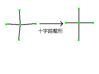
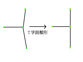
// T-Junction, Crossroad Correction (Recommended for reference lines. Also applicable for contours, but meaningless)
// Crossroad shaping
//   │           │
//  \|/   →  ─┼─
//    │           │
//   │           │
//  ─┤/   →  ─┼─
//    │           │
// Input
//    double        amaxmove;    // Maximum movement distance of adjacent vertices
//  double        anglemin;    // Minimum angle of straight parts centered on the smallest intersection point (PAI - anglemin to PAI + anglemin)
// Return Value
//  0....Normal completion
//  Negative...Error
int                 mcorrectCcross(double amaxmove,double anglemin);
// T-Junction shaping
//  ̄\/ ̄     ─┬─
//    │     →   │
//    │           │
// Input
//    double        amaxmove;    // Maximum movement distance of adjacent vertices
//  double        anglemin;    // Minimum angle of straight parts centered on the smallest intersection point (PAI - anglemin to PAI + anglemin)
// Return Value
//  0....Normal completion
//  Negative...Error
int                 mcorrectTcross(double amaxmove,double anglemin);
// Isolate processing (Recommended for reference lines. Also applicable for contours, but meaningless)
//   Processing to convert four lines intersecting at a crossroad into two intersecting lines, represented as →↑, and
//     three lines intersecting at a T-junction into two T-shaped intersecting lines, represented as →↓. The angle deviation between the connecting lines should be within 30 degrees.
// Return Value
//  0....Normal completion
//  Negative...Error
int                 misolatepolyline();
Sample
// Intersection correction - movement of 0.15mm, up to 15 degrees of deviation from vertical and horizontal intersections
// CALibVector::plib
plib->mcorrectTcross(0.15 * dpi / 25.4,15 * PAI / 180);
plib->misolatepolyline();
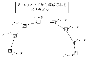
A spline curve that passes through the original vertices will deviate from the edges as shown in the figure below.
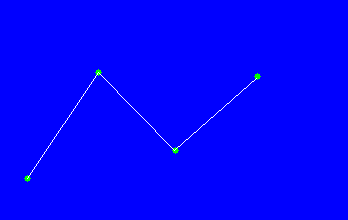
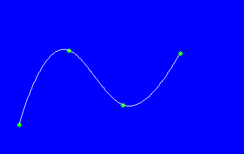
Original polyline Spline approximation curve
Therefore, ALIBVECTOR adds auxiliary points near the vertices to ensure that the spline curve generated is close to the original polyline.
Information about the spline approximation can be obtained in two ways:
Of course, if needed, it is also possible to spline approximate without changing the original vertices.
Reference
// Spline approximation
// After conversion, obtain the coordinates of the spline-interpolated vertices using the specific API (mgetsplinevertexofpolyline).
// Input
//    int                splinestep;   Interpolate one side using splinestep points.
//                                     Note that if the connection with the front and back is complicated, the number of interpolation points may be increased rather than the splinestep.
// Return
//  0....Normal completion
//  Negative...Error
int                 mconvertspline(int splinestep);
// Line conversion
// Convert back to line approximation after arc approximation or spline approximation (does not affect the acquisition of vertex coordinates, but affects the return value of mgetconvertinfo(int offsetpolyline)).
// Return
//  0....Normal completion
//  Negative...Error
void                mconvertline();
Sample
// Spline approximation, interpolate between vertices in 10 steps
// CALibVector::plib
plib->mconvertspline(10);
Reference
// Arc approximation
// Get the coordinates of the start and end points of the edge with bulging information using the API (mgetsideofpolyline)
// Input
//     double            aminradius;        Minimum radius for arc approximation (arc with radius smaller than the minimum radius is not targeted) (unit: pixels)
//     double            amaxradius;        Maximum radius for arc approximation (arc with radius larger than the maximum radius is not targeted) (unit: pixels)
//                                          Arcs smaller than the minimum radius are closer to acute angles, and arcs larger than the maximum radius are closer to straight lines
//     int               checkflag;         Flag to check if there are contour pixels below the arc
//     double            checkrange;        OK if there are contour pixels within ±checkrange pixels when checking
// Return value
//  0....Normal completion
//  Negative...Error
int                 mconvertarc(double aminradius,double amaxradius,int checkflag,double checkrange);
// Line conversion
// Convert back to line approximation after arc approximation or spline approximation (does not affect the acquisition of vertex coordinates, but affects the return value of mgetconvertinfo(int offsetpolyline))
// Return value
//  0....Normal completion
//  Negative...Error
void                mconvertline();
Sample
// Approximate as arcs from 1mm to 1000mm in radius.
// Check if bit1 exists within 2 pixels from the center of the arc when approximated as an arc.
// CALibVector::plib
plib->mconvertarc(1.0 * dpi / 25.4,1000.0 * dpi / 25.4,1,2);
Reference
// 1. Get the number of polylines
// Return value
//   Number of polylines
    int mgetpolylinenum();
// 2. Access function for each vertex of the polyline (if you access the vertex, you cannot obtain information for representing arcs. It is obtained as a continuous line segment)
//       In the case of a closed curve, the starting point coordinates are equal to the endpoint coordinates
// 2.1. Get the number of vertices
// Input
//    int offsetpolyline: Polyline offset (0 to mgetpolylinenum() - 1)
//                        Exception occurs if out of range is specified
// Return value
// Number of vertices in the specified polyline (0 if invalid polyline)
// e.g. In the case of a closed curve, the starting point and the endpoint coincide, so it becomes 5 vertices for a square, for example.
    int mgetvertexnumofpolyline(int offsetpolyline);
// 2.2. Get the coordinates of the vertex
// Input
//    int offsetpolyline: Polyline offset (0 to mgetpolylinenum() - 1)
//    int offsetvertex: Vertex offset (0 to mgetvertexnumofpolyline(offsetpolyline) - 1)
// Output
//    int* x: Vertex coordinate (in pixels)
//    int* y: Vertex coordinate (in pixels)
//            Exception occurs if out of range is specified
    void mgetvertexofpolyline(int offsetpolyline, int offsetvertex, int& x, int& y);
// Get in mm units (using dpi information in msetdocument conversion)
// Output
//    double* x: Vertex coordinate (in mm)
//    double* y: Vertex coordinate (in mm)
    void mgetvertexofpolylinemm(int offsetpolyline, int offsetvertex, double& x, double& y);
// 2.3. Get conversion information of polyline (whether spline approximation or arc approximation is used, spline and arc approximation can be canceled by msetline)
// Return value
//    0....Line segment conversion
//    1....Arc approximation
//    2....Spline approximation
//    3....Arc approximation + Spline approximation (dxf output has priority on spline)
    int mgetconvertinfo(int offsetpolyline);
// 3. Access function for each valid polyline (edge information includes information for representing arcs)
// 3.1. Get the number of edges
// Input
//    int offsetpolyline: Polyline offset (0 to mgetpolylinenum() - 1)
//                        Exception occurs if out of range is specified
// Return value
// Number of edges in the specified polyline (0 if invalid polyline)
    int mgetsidenumofpolyline(int offsetpolyline);
// 3.2. Get the starting and ending coordinates of the edge
// Input
//    int offsetpolyline: Polyline offset (0 to mgetpolylinenum() - 1)
//    int offsetside: Edge offset (0 to mgetsidenumofpolyline(offsetpolyline) - 1)
//                    Exception occurs if out of range is specified
// Output
//    int* x1, y1, x2, y2: Coordinates of the starting and ending points (in pixels)
//    double* radius: Radius when approximating as an arc (in pixels)
//    double* cx, cy: Center coordinates when approximating as an arc (in pixels)
    void mgetsideofpolyline(int offsetpolyline, int offsetside, int& x1, int& y1, int& x2, int& y2, double& radius, double& cx, double& cy);
// Get in mm units (using dpi information in msetdocument conversion)
// Output
//    double* x1, y1, x2, y2: Coordinates of the starting and ending points (in mm)
//    double* radius: Radius when approximating as an arc (in mm)
//    double* cx, cy: Center coordinates when approximating as an arc (in mm)
    void mgetsideofpolylinemm(int offsetpolyline, int offsetside, double& x1, double& y1, double& x2, double& y2, double& radius, double& cx, double& cy);
// 5.......Function to access the 3rd order spline vertices of each polyline
// Returns a negative number as the number of vertices if the polyline is not approximated by a spline
// In the case of a closed curve, the starting coordinates are equal to the ending coordinates
// 5.1.....Get the number of vertices
// Input
//    int        offsetpolyline;        Polyline offset (0 to mgetpolylinenum() - 1)
//                                Exception occurs if specified offset is out of range
// Return value
// Number of spline vertices for the specified polyline (0 if it is an invalid polyline (no need to output))
    int                 mgetsplinevertexnumofpolyline1(int offsetpolyline);
    int                 mgetsplinevertexnumofpolyline2(int offsetpolyline);
// 5.2.....Get the coordinates of the auxiliary points
//   In the case of a spline, they are returned as double values, so be careful
// Input
//    int        offsetpolyline;      Polyline offset (0 to mgetpolylinenum() - 1)
//    int        offsetvertex;        Vertex offset (0 to mgetvertexnumofpolyline(offsetpolyline) - 1)
//                    Exception occurs if specified offset is out of range
// Output
//    double*    x;     Coordinates of the auxiliary point (in pixels)
//    double*    y;     Coordinates of the auxiliary point (in pixels)
    void                mgetsplinevertexofpolyline1(int offsetpolyline,int offsetvertex,double& x,double& y);
// Get in mm units (convert using dpi information in msetdocument)
// Output
//    double*    x;     Coordinates of the auxiliary point (in mm)
//    double*    y;     Coordinates of the auxiliary point (in mm)
    void                mgetsplinevertexofpolyline1mm(int offsetpolyline,int offsetvertex,double& x,double& y);
// 5.3.....Get the coordinates of the polyline vertices approximated by the spline curve
//   In the case of a spline, they are returned as double values, so be careful
// Input
//    int        offsetpolyline;      Polyline offset (0 to mgetpolylinenum() - 1)
//    int        offsetvertex;        Vertex offset (0 to mgetvertexnumofpolyline(offsetpolyline) - 1)
//                    Exception occurs if specified offset is out of range
// Output
//    double*    x;     Coordinates of the vertex (in pixels)
//    double*    y;     Coordinates of the vertex (in pixels)
    void                mgetsplinevertexofpolyline2(int offsetpolyline,int offsetvertex,double& x,double& y);
// Get in mm units (convert using dpi information in msetdocument)
// Output
//    double*    x;     Coordinates of the vertex (in mm)
//    double*    y;     Coordinates of the vertex (in mm)
    void                mgetsplinevertexofpolyline2mm(int offsetpolyline,int offsetvertex,double& x,double& y);
Sample
///////////////////
// Drawing Polylines
// Implementing a method in the CScancalcDoc class that calls the CALibVector class with the same method name and arguments
void CScancalcView::mDrawPolyline(CDC* pDC)
{
        CScancalcDoc* pDoc = GetDocument();
        if(pDoc->mgetimagenum() == 0) return;
        if(!pDoc->misinitrastervectorconversion()) return;
        int     polylinenum = pDoc->mgetpolylinenum();
        if(polylinenum == 0) return;

        CPen*   pen[12];
        pen[0] = new CPen(PS_SOLID,2,RGB(255,127,127));
        pen[1] = new CPen(PS_SOLID,2,RGB(127,255,127));
        pen[2] = new CPen(PS_SOLID,2,RGB(127,127,255));
        pen[3] = new CPen(PS_SOLID,2,RGB(255,255,127));
        pen[4] = new CPen(PS_SOLID,2,RGB(127,255,255));
        pen[5] = new CPen(PS_SOLID,2,RGB(255,127,255));
        pen[6] = new CPen(PS_SOLID,2,RGB(255,0,0));
        pen[7] = new CPen(PS_SOLID,2,RGB(0,255,0));
        pen[8] = new CPen(PS_SOLID,2,RGB(0,0,255));
        pen[9] = new CPen(PS_SOLID,2,RGB(255,255,0));
        pen[10] = new CPen(PS_SOLID,2,RGB(0,255,255));
        pen[11] = new CPen(PS_SOLID,2,RGB(255,0,255));

        CPen*   oldPen = pDC->SelectObject(pen[0]);
        for(int i = 0 ; i < polylinenum ; i++) {
                pDC->SelectObject(pen[i % 12]);
                if(pDoc->mgetvertexnumofpolyline(i) > 0) {
                        // Prioritizing splines
                        if(pDoc->mgetconvertinfo(i) & 2) {
                                mDrawSpline1(pDC,i);
                        }
                        else if(pDoc->mgetconvertinfo(i) & 1) {
                                mDrawFitcurve1(pDC,i);
                        }
                        else {
                                mDrawPolyline1(pDC,i);
                        }
                }
        }
        pDC->SelectObject(oldPen);
        for(i = 0 ; i < 12 ; i++) {
                delete pen[i];
        }
}
void CScancalcView::mDrawPolyline1(CDC* pDC,int offset)
{
        CScancalcDoc*   pDoc = GetDocument();

        int     sidenum = pDoc->mgetsidenumofpolyline(offset);
        CRect   crect,vrect;
        GetClientRect(&crect);
        vrect.left = mscrollposx;
        vrect.top = mscrollposy;
        vrect.right = (long)(vrect.left + crect.right / mag);
        vrect.bottom = (long)(vrect.top + crect.bottom / mag);
        for(int i = 0 ; i < sidenum ; i++) {
                int     x1,y1,x2,y2;
                double  cx,cy,radius;
                pDoc->mgetsideofpolyline(offset,i,x1,y1,x2,y2,radius,cx,cy);
                if(mcheckvisible(vrect,x1,y1,x2,y2)) {
                        if(i == 0) mDrawNode(pDC,x1,y1);
                        pDC->MoveTo((long)((x1 - mscrollposx) * mag),(long)((y1 - mscrollposy) * mag));
                        pDC->LineTo((long)((x2 - mscrollposx) * mag),(long)((y2 - mscrollposy) * mag));
                        mDrawNode(pDC,x2,y2);
                }
        }
}
void CScancalcView::mDrawSpline1(CDC* pDC,int offset)
{
        CScancalcDoc*   pDoc = GetDocument();

        int     vertexnum = pDoc->mgetsplinevertexnumofpolyline(offset);
        CRect   crect,vrect;
        GetClientRect(&crect);
        vrect.left = mscrollposx;
        vrect.top = mscrollposy;
        vrect.right = (long)(vrect.left + crect.right / mag);
        vrect.bottom = (long)(vrect.top + crect.bottom / mag);

        for(int i = 0 ; i < vertexnum - 1 ; i++) {
                double  x1,y1,x2,y2;
                pDoc->mgetsplinevertexofpolyline(offset,i,x1,y1);
                pDoc->mgetsplinevertexofpolyline(offset,i + 1,x2,y2);
                if(mcheckvisible(vrect,(int)x1,(int)y1,(int)x2,(int)y2)) {
                        pDC->MoveTo((long)((x1 - mscrollposx) * mag),(long)((y1 - mscrollposy) * mag));
                        pDC->LineTo((long)((x2 - mscrollposx) * mag),(long)((y2 - mscrollposy) * mag));
                }
        }
        vertexnum = pDoc->mgetsidenumofpolyline(offset);
        for(i = 0 ; i < vertexnum ; i++) {
                int             x1,y1;
                pDoc->mgetvertexofpolyline(offset,i,x1,y1);
                if(mcheckvisible(vrect,(int)(x1 - 3 / mag),(int)(y1 - 3 / mag),(int)(x1 + 3 / mag),(int)(y1 + 3 / mag))) {
                        mDrawNode(pDC,x1,y1);
                }
        }
}
void CScancalcView::mDrawFitcurve1(CDC* pDC, int offset)
{
        CScancalcDoc*   pDoc = GetDocument();

        int             sidenum = pDoc->mgetsidenumofpolyline(offset);
        CRect           crect, vrect;
        GetClientRect(&crect);
        vrect.left = mscrollposx;
        vrect.top = mscrollposy;
        vrect.right = (long)(vrect.left + crect.right / mag);
        vrect.bottom = (long)(vrect.top + crect.bottom / mag);
        for(int i = 0 ; i < sidenum ; i++) {
                int             x1, y1, x2, y2;
                double          cx, cy, radius;
                pDoc->mgetsideofpolyline(offset, i, x1, y1, x2, y2, radius, cx, cy);
                if(mcheckvisible(vrect, x1, y1, x2, y2)) {
                        if(i == 0) mDrawNode(pDC, x1, y1);
                        if(radius > 0.0) {
                                int             x3, y3, x4, y4;
                                x3 = (int)(((cx - radius) - mscrollposx) * mag);
                                y3 = (int)(((cy - radius) - mscrollposy) * mag);
                                x4 = (int)(((cx + radius) - mscrollposx) * mag);
                                y4 = (int)(((cy + radius) - mscrollposy) * mag);
                                // The width and height of the rectangle must be between 2 and 32767
                                int             width = x4 - x3;
                                int             height = y4 - y3;
                                if(width < 2 || 32767 < width || height < 2 || 32767 < height) {
                                        pDC->MoveTo((long)((x1 - mscrollposx) * mag), (long)((y1 - mscrollposy) * mag));
                                        pDC->LineTo((long)((x2 - mscrollposx) * mag), (long)((y2 - mscrollposy) * mag));
                                }
                                else {
                                        // CDC::Arc is counter-clockwise and the center of the ellipse must be to the left of the direction of travel
                                        // If (cx,cy) is on the right side of (x1,y1)->(x2,y2), reverse the start and end points
                                        if(pDoc->mccw(x1,y1,x2,y2,cx,cy,0.0) == 1) {
                                                int i1 = x1; x1 = x2; x2 = i1;
                                                i1 = y1; y1 = y2; y2 = i1;
                                        }
                                        pDC->Arc(x3, y3, x4, y4,
                                                (int)((x1 - mscrollposx) * mag), (int)((y1 - mscrollposy) * mag),
                                                (int)((x2 - mscrollposx) * mag), (int)((y2 - mscrollposy) * mag));
                                }
                        }
                        else {
                                pDC->MoveTo((long)((x1 - mscrollposx) * mag), (long)((y1 - mscrollposy) * mag));
                                pDC->LineTo((long)((x2 - mscrollposx) * mag), (long)((y2 - mscrollposy) * mag));
                        }
                        mDrawNode(pDC, x2, y2);
                }
        }
}
void CScancalcView::mDrawNode(CDC* pDC, int x1, int y1)
{
        CPen    pen1(PS_SOLID,3,RGB(255,127,127));
        CPen*   oldPen = pDC->SelectObject(&pen1);
// Draw the rectangle
        x1 = (int)((x1 - mscrollposx) * mag);
        y1 = (int)((y1 - mscrollposy) * mag);
        pDC->Rectangle(x1 - 3, y1 - 3, x1 + 3, y1 + 3);
        pDC->SelectObject(oldPen);
}
// Whether it needs to be displayed or not
// Inputs
//      RECT    arect;                          Display area in pixel coordinates
//      int     x1,int y1,int x2,int y2;        Link in pixel coordinates
int CScancalcView::mcheckvisible(CRect arect,int x1,int y1,int x2,int y2)
{
        // Calculate the coordinates of the enclosing square of the link
        int             cx = (x1 + x2) / 2;
        int             cy = (y1 + y2) / 2;
        int             width = x2 - x1 + 1;
        int             height = y2 - y1 + 1;

        if(width < 0) width = -width;
        if(height < 0) height = -height;
        int             sx1,sy1,sx2,sy2;
        if(width > height) {
                sx1 = cx - width / 2;
                sx2 = cx + width / 2;
                sy1 = cy - width / 2;
                sy2 = cy + width / 2;
        }
        else {
                sx1 = cx - height / 2;
                sx2 = cx + height / 2;
                sy1 = cy - height / 2;
                sy2 = cy + height / 2;
        }
// Check if any part of the enclosing square is within the display area
        if(sx2 < arect.left) return(0);
        if(arect.right < sx1) return(0);
        if(sy2 < arect.top) return(0);
        if(arect.bottom < sy1) return(0);
        return(1);
}
// Parent class of the document class
//- Return value
//- -1... Point (x3, y3) is on the left side of segment (x1, y1)-(x2, y2) in terms of the direction
//- 1... Point (x3, y3) is on the right side of segment (x1, y1)-(x2, y2) in terms of the direction
//- Point (x3, y3) is on the segment (x1, y1)-(x2, y2)
//- -1... Segment (x3, y3)-(x1, y1)-(x2, y2) is on the same line
//- 0.... Segment (x1, y1)-(x3, y3)-(x2, y2) is on the same line
//- 1.... Segment (x1, y1)-(x2, y2)-(x3, y3) is on the same line
int CALDataVector::mccw(double x1,double y1,double x2,double y2,double x3,double y3,double zero)
{
        double          dx12 = x2 - x1;
        double          dy12 = y2 - y1;
        double          dx13 = x3 - x1;
        double          dy13 = y3 - y1;

        double          f = dx12 * dy13 - dy12 * dx13;
        if(f > zero) return 1;
        else if(f < -zero) return -1;
        else {
                if(dx12 * dx13 < 0.0) return -1;
                if(dy12 * dy13 < 0.0) return -1;
                if(dx12 * dx12 + dy12 * dy12 < dx13 * dx13 + dy13 * dy13) return 1;
                return 0;
        }
}
Table of Contents
Reference
// Save DXF file
// Input
//  char*       filename;           DXF file name (full path)
//  int         width;              Image width (in pixels)
//  int         height;             Image height (in pixels)
//  int         dpi;                Image resolution (converted to mm in the DXF file)
//  int         r12flag;            0...Save DXF file with simple header
//                                  1...Save DXF file with R12 header
//  int         linearcflag;        0...Save POLYLINE entity as the output
//                                  1...Save LINE/ARC entity as the output
// Return value
//  0....Normal completion
//  Negative number...Error
int                 msavedxf(char* filename,int width,int height,int dpi,int r12flag = 0,int linearcflag = 0);
Sample
// Save DXF file
// Save the result of raster-vector conversion of a 2440×1820 pixel, 400 dpi image
// to CALibVector::plib
int i1 = plib->msavefxf("c:\\data\\sample.dxf",2440,1820,400);
Reference
  int mabstractcenterlineEX(double threshold,
      int flag,              // 0x00000000... Do not perform any special action
                             // 0x00000020... Perform integration of extremely close points (default is ON)
                             // 0x00000040... Generate 2-point short vectors (default is OFF)
      int higelength,        // Length of the whiskers to be removed (in pixels, no removal if 0)
      double shortvectormax,    // Maximum length of short vectors to be removed
      double autojointshort,    // Maximum distance for automatic connection within an angle deviation of 90 degrees (in pixels, no connection if 0.0)
      double autojointlong,     // Maximum distance for automatic connection within an angle deviation of autojointangle (in pixels, no connection if 0.0)
      double autojointangle,    // Angle deviation of the two edges that can be automatically connected (in radians)
      double integratedist);    // Maximum distance for merging nearby crossing points (in pixels)
Sample
// Notify the width (mwidth), scanline size (mscanlinesize), height (mheight), resolution (mdpi), and top address (mdata) of the image
// CALibVector::plib
#include "alibvector.h"
#include "errcode.h"
plib->msetdocument(mwidth,mscanlinesize,mheight,mdpi,mdata);
int i1 = plib->mabstractcenterlineEX(mapploxthreshold,0x00000040,       // Also generate 2-point short vectors
                                                                         // Do not connect nodes within 2 pixels
                           2,                                            // Remove whiskers with a length of 2 pixels
                           0,                                            // Do not remove short vectors
                           (0.25 * mdpi) / 25.4,                         // Connect broken lines up to 0.25mm apart (within an angle of 90 degrees, even if they make a right angle), converted to pixels
                           (1.25 * mdpi) / 25.4,                         // Connect broken lines up to 1.25mm apart (within an angle of 40 degrees, connecting those that are close to horizontal), converted to pixels
                           40.0 * PAI / 180.0,                           // Specify the above angle in radians
                           (0.5 * mdpi) / 25.4);                         // Merge two intersecting points within 0.5mm
if(i1 < 0) {
    // Error;
}
...
detailed explanation
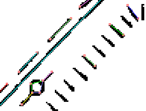
The results of connecting dashed lines with the above argument are as follows:
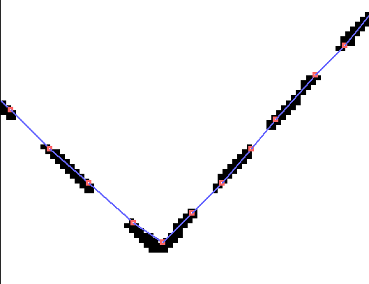
When changing 1.25 to 0.75, the dashed line intervals are about 1mm, so it looks like this.
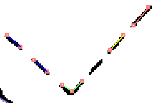
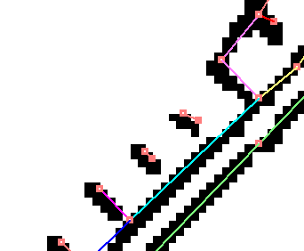
When generating a 2-point short vector, an extremely short line is created as shown below.
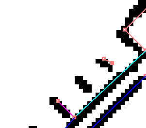
When not generating a 2-point short vector in the case of 0x00000040 → 0x00000000, an extremely short line is not created as shown below.
Short vectors longer than 2 pixels can also be removed using the shortvectormax argument.
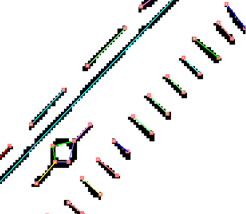
When changing the fourth argument to 0 → (2.00 * mdpi) / 25.4, short vectors below 2mm disappear and it becomes as follows:
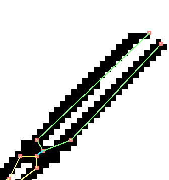
In addition to the joints, there is also a flag to unconditionally merge two nodes within 2 pixels of each other. In the above sample, the flag is off, so it will look like this:
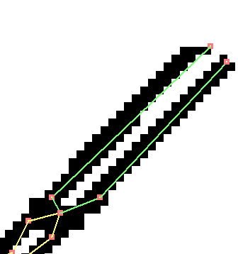
When changing the flag from 0x00000040 to 0x00000060, it will change as follows:
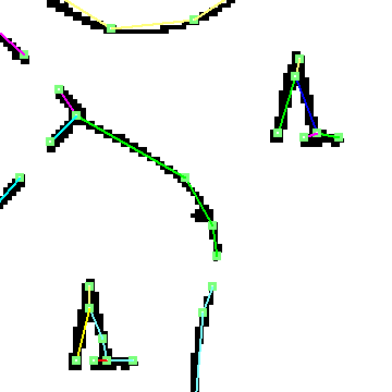
int         flag,           // 0x0000031f...not disclosed in alibvector.dll
                            // 0x00000020...integration of very close points (previous version)
                            // 0x00000040...generation of short vectors (previous version)
                            // The following flags are used in the 2007 version update
                            // 0x00000080...vectorization of isolated points
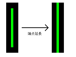
                            // 0x00000400...end point extension processing
                            // 0x00000800...1-pixel diagonals
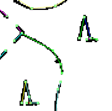
                            // 0x00010000...※ removal of unnecessary vertices on straight lines
                            // 0x00020000...※ removal of sharp whiskers
                            // 0x00040000...※ improved correction for T-intersections and crosses
                            // 0x00080000...※ coordinate correction processing
                            // 0x01000000...acute angle emphasis
                            // 0x02000000...acute angle emphasis with smoothing
                            // 0x10000000...※ correction for close parallel lines
 →
→
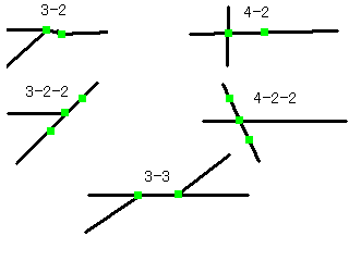
// Improved T-junction and crossroad correction
// int          flag22;             Default supports 3-2 case/4-2 case
//                                  bit0...Supports 3-2-2/4-2-2 cases
//                                  bit1...Supports extended 3-2 case
//                                  bit2...Supports extended 3-2-2 case
//                                  bit3...Supports 3-3 case
//                                  2 represents intermediate point - - intermediate point - -
//                                  3 represents T-junction
//                                  4 represents crossroad
// double       tunecrossmax1;	    Maximum distance between nodes for 3-2/3-3/4-2 cases (in pixels)
// double       tunecrossmax2;	    Maximum distance between nodes for 3-2-2/4-2-2 cases (in pixels)
// Return value
//  0 or greater     Number of merged nodes
//  Negative         Error
int             mtunecrossrepeat(int flag22,double tunecrossmax1,double tunecrossmax2);
// Removal of unnecessary vertices on straight lines
// □------□------□
//  1      2      3
//         ↓
// □--------------□
//  double      angle;              Angle between 1->2 and 2->3 (in radians)
//  double      probelen;           Check if the coordinate of the foot of the perpendicular dropped from 2 to 1->3 is on the raster's foreground color
//                                  If there is bit1 within probelen pixels from the foot of the perpendicular, it is acceptable
// Return value
//  0 or greater     Number of removed nodes
//  Negative         Error
int 				mdeletewastepointrepeat(double angle,double probelen);
// Remove if the maximum point movement distance is reached and the pixel density is greater than or equal to amindens
//  double      amaxmode;           Maximum movement distance of 2 (in pixels)
//  double      amindens;           Luminance value at the destination of 2 (0.0 to 1.0)
// Return value
//  0 or greater     Number of removed nodes
//  Negative         Error
int 				mdeletewastepointsimrepeat(double amaxmove,double amindens);
// Parallel line shaping filter
// Return value
//  0           Normal termination
//  Negative    Error
int					mparallelfilter();
// Dashed Line Recognition
//  int         aminnum;            Minimum number of dashed elements
//  double      amaxlen;            Maximum length of dashed elements
//  double      amaxgap;            Maximum interval between dashed elements
//  double      amaxangle;          Maximum deviation angle of dashed elements and gaps
// Return Value
//  0 or more    Number of generated dashed lines
//  Negative     Error
int                 mconvertdotline(int aminnum,double amaxlen,double amaxgap,double amaxangle);
To access each individual line element of the dashed line, use the API mgetsideofdotline, which is similar to mgetsideofpolyline.
// Get the start and end coordinates of an edge
// Input
//    int        offsetpolyline;    Polyline offset (0 to mgetpolylinenum() - 1)
//    int        offsetside;        Edge offset (0 to mgetsidenumofpolyline(offsetpolyline) - 1)
//                    Exceptions will occur if you specify out of range values
// Output
//    int&       x1,y1,x2,y2;       Coordinates of the start and end points (in pixels)
// Return Value
//  1....Dashed element of the dashed line
//  0....Gap between dashed elements of the dashed line
    int                 mgetsideofdotline(int offsetpolyline,int offsetside,int& x1,int& y1,int& x2,int& y2);
// Get in mm units (using dpi information from msetdocument for conversion)
// Output
//    double&    x1,y1,x2,y2;       Coordinates of the start and end points (in mm)
// Return Value
//  1....Dashed element of the dashed line
//  0....Gap between dashed elements of the dashed line
    int                 mgetsideofdotlinemm(int offsetpolyline,int offsetside,double& x1,double& y1,double& x2,double& y2);
// Clear selection of nodes (vertices)
// Clear the selection state of all nodes
void				malibclearselectnode();
// Select nodes (vertices)
// Select nodes (vertices) within the rectangle (left, top) - (right, bottom)
// Return
//  Number of selected nodes (vertices)
int					malibselectnode(int left,int top,int right,int bottom);
// Reference the selection state of nodes
// Input
//    int       offsetpolyline;     Polyline offset (0 to mgetpolylinenum() - 1)
//    int       offsetvertex;       Vertex offset (0 to mgetvertexnumofpolyline(offsetpolyline) - 1)
// 1....The node is in the selection state
// 0....The node is not in the selection state
int					malibisselectnode(int offsetpolyline,int offsetvertex);
// Return the number of selected nodes
int					mgetselectednodenum();
// Return the number of nodes
int					mgetnodenum();
// Delete selected nodes
// Return...Number of deleted nodes
int					mdeleteselectednode();
// Delete polylines that include selected nodes
// Delete selected nodes
// Return...Number of deleted polylines
int					mdeleteselectedpolyline();
// Delete all polylines
// Return...Number of deleted polylines
int					mdeleteallpolyline();
// Approximate arcs
// Get the coordinates with the API (mgetsideofpolyline) that obtains the coordinates with bulging information
// Input
//  int             offsetpolyline;     Polyline offset (0 to mgetpolylinenum() - 1)
//  double          aminradius;         Minimum radius for arc approximation (Those that become arcs with radii smaller than the minimum radius are not targeted) (Unit: pixels)
//  double          amaxradius;         Maximum radius for arc approximation (Those that become arcs with radii larger than the maximum radius are not targeted) (Unit: pixels)
//                                      Those with radii smaller than the minimum radius are near acute angles, and those with radii larger than the maximum radius are near straight lines
//  int             checkflag;          Check if there are outline pixels under the arc
//  double          checkrange;         OK if there are outline pixels within ±checkrange pixels during the check
// Return
//  0....Normal termination
//  Negative...Error
int                 mconvertarc(int offsetpolyline,double aminradius,double amaxradius,int checkflag,double checkrange);
// Approximate splines
// After conversion, get the coordinates of the vertices that are spline-interpolated with the dedicated API (mgetsplinevertexofpolyline)
// Input
//  int             offsetpolyline;     Polyline offset (0 to mgetpolylinenum() - 1)
//  int             splinestep;         Interpolate so that each edge becomes splinestep.
//                                      Be aware that if the connection with the previous and next edges is complicated, more interpolation points may be added than splinestep.
// Return
//  0....Normal termination
//  Negative...Error
int                 mconvertspline(int offsetpolyline,int splinestep);
// Approximate line segments
// Return to line segment approximation after arc approximation or spline approximation (Does not affect the vertex coordinate acquisition, but affects the edge attribute and msavedxf)
// Input
//  int             offsetpolyline;     Polyline offset (0 to mgetpolylinenum() - 1)
// Return
//  0....Normal termination
//  Negative...Error
void                mconvertline(int offsetpolyline);
Reference 1 (planned specification: character, line, and area separation function)
Separate the drawing into line shapes, area shapes, and character string shapes. Convert line shapes to core vector lines and area shapes to contour vector shapes.
First, separate the character string shapes using the amincharnum/amaxcharsize parameters. If amincharnum is greater than or equal to 10000, the separation of character string shapes is not performed. Separation of character string shapes is avoided when there are dashed lines, as dashed lines and character strings can be easily misidentified.
Next, separate the line shapes and area shapes using the maximum line width (linewidthmax) parameter.
Line shapes are converted using the same process as mabstractcenterlineEX, using the arguments that are equal to or below the threshold.
Area shapes are converted using moptimizeoutline. The argument for moptimizeoutline is set to 2 if the removal of isolated points (8-connected) / isolated holes (4-connected) is turned on, and 1 if it is turned off.
// Recognition of vector conversion for polygon shapes, line shapes, and string shapes
int CALibVector::mabstractbothline(
	double  linewidthmax,       // Shapes with a line width exceeding linewidthmax are recognized as polygon shapes
	int     amincharnum,        // Minimum number of primitives in a string (if equal to or greater than 10000, the string is not separated)
	double  amaxcharsize,       // Maximum character size
	double  threshold,          // Approximation parameter (a value greater than 0 and smaller than 10.0, recommended value 0.8-2.0)
	int		flag,				// 0x00000001...Joint at closest points;
								// 0x00000002...Joint at nearby points
								// 0x00000004...Joint at intersections
								// 0x00000008...Beard removal
								// 0x00000010...Integration of nearby intersections
								// 0x00000020...Integration of extremely close points
								// 0x00000040...Generation of short vectors
								// 0x00000080...Vectorization of isolated points
								// 0x00000100...Correction of TandT intersections
								// 0x00000200...Straight joint
								// 0x00000400...Endpoint extension processing
								// 0x00000800...1-pixel diagonal
								// 0x00010000...※ Removal of unnecessary vertices on straight lines (weak)
								// 0x00020000...※ Removal of sharp angle beards
								// 0x00040000...※ Improved correction of T-crossroads intersections
								// 0x01000000...acute angle emphasis
								// 0x02000000...acute angle emphasis with smoothing
								// 0x10000000...※ Correction of nearby parallel lines
								// 0x20000000...※ Removal of 1-pixel isolated points (8-connected)/isolated holes (4-connected)
    int     higelength,        // Length of beard to be removed (in pixels, do not remove if 0)
    double  shortvectormax,    // Maximum length of short vectors to be removed
    double  autojointshort,    // Maximum distance for automatic connection up to angle deviation of 90 degrees (in pixels, no connection if 0.0)
    double  autojointlong,     // Maximum distance for automatic connection up to angle deviation of autojointangle (in pixels, no connection if 0.0)
    double  autojointangle,    // Angle deviation for automatic connection of 2 sides (in radians)
    double  integratedist);    // Maximum distance for integration of nearby intersections (in pixels)
Reference 2
Apply automatic recognition vector conversion to some figures.
There are two ways to select figures: rectangle hook and rectangle inner. With the rectangle hook, the figures within the rectangle including the frame are converted. With the rectangle inner, the figures within the rectangle are converted, and the figures on the frame are excluded from the conversion.
// Convert the objects that overlap the inside and frame of the rectangle into contour and core lines automatically
// Input
//  double          linewidthmax;       Figures with a linewidth greater than linewidthmax are judged as surface figures
//  int             x1, y1, x2, y2;     Coordinates of the diagonal of the rectangle
//  double          threshold;...       Refer to mabstractbothline
// Return value
//  0.....Normal termination
//  Negative value....Error
int                 mabstractbothlinerecthook(
    double linewidthmax,       // Maximum line width
    int    x1,
    int    y1,
    int    x2,
    int    y2,                 // Coordinates of the diagonal of the rectangle
    double threshold, int flag, int higelength, double shortvectormax,
    double autojointshort, double autojointlong, double autojointangle, double integratedist);
// Convert the objects that are completely contained within the rectangle into contour and core lines automatically
int                 mabstractbothlinerectinner(
    double linewidthmax,       // Maximum line width
    int    x1,
    int    y1,
    int    x2,
    int    y2,                 // Coordinates of the diagonal of the rectangle
    double threshold, int flag, int higelength, double shortvectormax,
    double autojointshort, double autojointlong, double autojointangle, double integratedist);
Reference 3 (Undo/Redo support)
// Get the buffer size to obtain the current state of the library
// Return value
//  Buffer size (to be allocated by the application)
size_t              mgetsavebuffersize();
// Obtain the current state of the library
// Purpose 1: Implement undo/redo function
//         2: Save and load the current working state in a custom file format
// Allocate the space for the buffer obtained by mgetsavebuffersize() before calling this function
// Input
//  char*&          ps1;                The address of the start of the buffer to obtain the state (to be allocated by the application)
void                msavebuffer(char*& ps1);
// Specify the current state of the library with the buffer
// Input
//  size_t          len;                Buffer size
//  char*&          ps1;                Address of the state buffer
// Return value
//  Negative value....Error
//  0.....Normal termination
int                 mloadbuffer(size_t& len, char*& ps1);
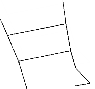
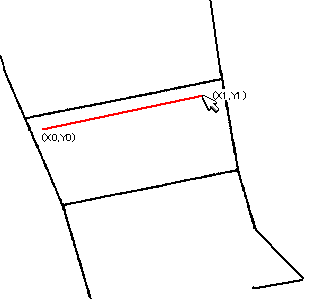
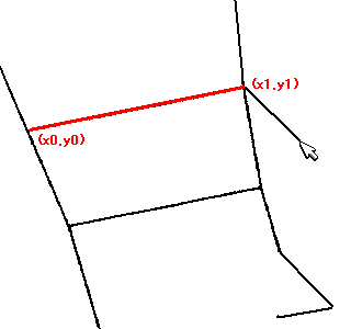
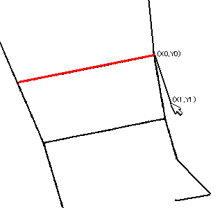
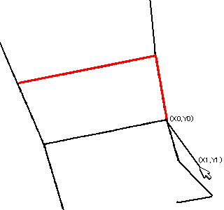
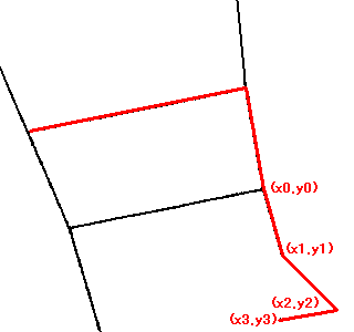
// Automatic Trace API
// Input
// double x1; Starting point x (specified by the user)
// double y1; Starting point y
// double x2; Ending point x (specified by the user)
// double y2; Ending point y
// Output
// int& vertexnum; Number of vertices
// double* px; Vertex coordinate array x
// double* py; Vertex coordinate array y
// Return Value
// 0....Success, the endpoint is an endpoint, specify another starting point for the next automatic trace
// 1....Success, the endpoint is an intersection, specify (px[vertexnum-1], py[vertexnum-1]) as the starting point for the next automatic trace
// Negative...Error
int mautotrace(double x1, double y1, double x2, double y2, int& vertexnum, double* px, double* py);
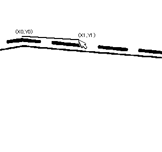
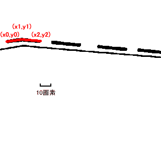
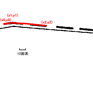
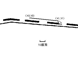
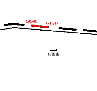
// Setting for Automatic Trace Parameters 1
// Setting parameters that comply with the core wire vector conversion
// Input
// Post-processing parameters
//  int             postprocessflag;    // 0x00010000...* Remove unnecessary vertices on a straight line
                                        // 0x00020000...* Remove acute angle hairs
                                        // 0x00040000...* Improved T-junction and crossroad correction
                                        // 0x10000000...* Correction of adjacent parallel lines
// Approximation parameters
//  double          threshold;          // Approximation parameter (the smaller the value, the higher the approximation accuracy, and the more vertices)
//                                         (values greater than 0 and less than 10.0, recommended value: 0.8-2.0)
// Automatic end-point connection parameters
//  double          autojointshort;     // Automatically connect very close end points.
//                                         Maximum value of the automatic connection distance that can be connected up to an angle deviation of 90 degrees (in unit pixels, if 0.0, no connection is made)
//  double          autojointlong;      // Automatically connect relatively close end points.
//                                         Maximum value of the automatic connection distance that can be connected up to an angle deviation of autojointangle (in unit pixels, if 0.0, no connection is made)
//  double          autojointangle;     // Angle deviation of two sides that can be automatically connected (in unit radians)
void                msetautotraceparameter1(int postprocessflag,double threshold,
	double autojointshort,double autojointlong,double autojointangle);
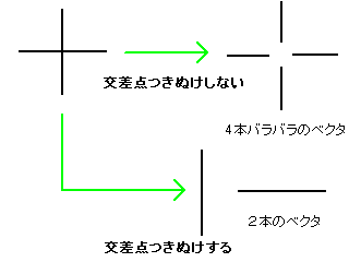
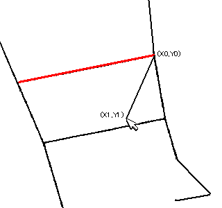
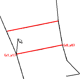
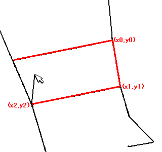
// Set automatic trace parameters 2
// Setting parameters specific to automatic trace
// Input
//  int             flag;               0x00000001...Cross intersection processing
//                                      0x00000002...Trace shortcut
//                                      See manual for details
//                                      0x00000004...Arc approximation
//                                      0x00000008...Arc fitting
//                                      0x00000010...Corner sharpening
//  double          penetrateangle;     Penetration angle at cross intersection (in radians)
//                                      Angle between the vectors just before and after the intersection (straight line if 0 degrees)
//  Automatic trace-specific whisker processing
//  double          ignorelength;       Ignore short vectors (length less than or equal to ignorelength) generated from branch points
//  Arc approximation related
//  double          aminradius;         Minimum radius for arc approximation (ignore arcs with a radius smaller than or equal to aminradius) (in pixels)
//  double          amaxradius;         Maximum radius for arc approximation (ignore arcs with a radius larger than or equal to amaxradius) (in pixels)
//                                      Parts close to acute angles have a radius smaller than or equal to the minimum radius, parts close to straight lines have a radius larger than or equal to the maximum radius
//  double          checkrange;         Check for the presence of pixels below the arc in arc approximation.
//                                      If contour pixels exist within ±checkrange pixels during the check, it is OK.
//                                      No check if 0.
//  Circle approximation related
//  double          radius;             Maximum radius for circle approximation (in pixels)
//  double          varrate;            If nodes (vertices) on the arc are within the estimated radius of the circle*(1.0±varrate), it is OK
//  double          fitrate;            If the number of nodes within varrate / the number of nodes on the arc is equal to or greater than fitrate, it is OK
//  Sharpening parameters
//                                      O(Newly added vertex)
//        Short side                  / \
//        O---O                       /   \
//       /     \                     /     \
//      /       Long side            /       \
//     /         \                 /         \
// ---O           O---   ==>   ---O           O---
//    double        longpixel;          Length of the long side in the diagram is equal to or greater than longpixel (in pixels)
//    double        shortpixel;         Length of the short side in the diagram is less than or equal to shortpixel (in pixels)
//    double        sharpenangle;       Angle formed by the two long sides is less than or equal to angle (in radians)
//    double        probelen;           Range to check if there are pixels of the shape under the newly added vertex (in pixels)
void                msetautotraceparameter2(int flag,double penetrateangle,
	double ignorelength,
	double aminradius,double amaxradius,double checkrange,
	double radius,double varrate,double fitrate,
	double longpixel,double shortpixel,double sharpenangle,double probelen);